Sunday, May 20, 2007

Robot Basics

The vast majority of robots do have several qualities in common. First of all, almost all robots have a movable body. Some only have motorized wheels, and others have dozens of movable segments, typically made of metal or plastic. Like the bones in your body, the individual segments are connected together with joints.

Robots spin wheels and pivot jointed segments with some sort of actuator. Some robots use electric motors and solenoids as actuators; some use a hydraulic system; and some use a pneumatic system (a system driven by compressed gases). Robots may use all these actuator types.


Photo courtesy NASA


A robotic hand, developed by NASA, is made up of metal segments moved by tiny motors. The hand is one of the most difficult structures to replicate in robotics

A robot needs a power source to drive these actuators. Most robots either have a battery or they plug into the wall. Hydraulic robots also need a pump to pressurize the hydraulic fluid, and pneumatic robots need an air compressor or compressed air tanks.


The actuators are all wired to an electrical circuit. The circuit powers electrical motors and solenoids directly, and it activates the hydraulic system by manipulating electrical valves. The valves determine the pressurized fluid's path through the machine. To move a hydraulic leg, for example, the robot's controller would open the valve leading from the fluid pump to a piston cylinder attached to that leg. The pressurized fluid would extend the piston, swiveling the leg forward. Typically, in order to move their segments in two directions, robots use pistons that can push both ways.

The robot's computer controls everything attached to the circuit. To move the robot, the computer switches on all the necessary motors and valves. Most robots are reprogrammable -- to change the robot's behavior, you simply write a new program to its computer.

Photo courtesy NASA JPL

NASA's Urbie climbing stairs

Not all robots have sensory systems, and few have the ability to see, hear, smell or taste. The most common robotic sense is the sense of movement -- the robot's ability to monitor its own motion. A standard design uses slotted wheels attached to the robot's joints. An LED on one side of the wheel shines a beam of light through the slots to a light sensor on the other side of the wheel. When the robot moves a particular joint, the slotted wheel turns. The slots break the light beam as the wheel spins. The light sensor reads the pattern of the flashing light and transmits the data to the computer. The computer can tell exactly how far the joint has swiveled based on this pattern. This is the same basic system used in computer mice.
These are the basic nuts and bolts of robotics. Roboticists can combine these elements in an infinite number of ways to create robots of unlimited complexity. In the next section, we'll look at one of the most popular designs, the robotic arm.

Parallel Port Basics

Parallel ports were originally developed by IBM as a way to connect a printer to your PC. When IBM was in the process of designing the PC, the company wanted the computer to work with printers offered by Centronics, a top printer manufacturer at the time. IBM decided not to use the same port interface on the computer that Centronics used on the printer.Instead, IBM engineers coupled a 25-pin connector, DB-25, with a 36-pin Centronics connector to create a special cable to connect the printer to the computer. Other printer manufacturers ended up adopting the Centronics interface, making this strange hybrid cable an unlikely de facto standard.
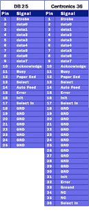
When a PC sends data to a printer or other device using a parallel port, it sends 8 bits of data (1 byte) at a time. These 8 bits are transmitted parallel to each other, as opposed to the same eight bits being transmitted serially (all in a single row) through a serial port. The standard parallel port is capable of sending 50 to 100 kilobytes of data per second.

Let's take a closer look at what each pin does when used with a printer:
  • Pin 1 carries the strobe signal. It maintains a level of between 2.8 and 5 volts, but drops below 0.5 volts whenever the computer sends a byte of data. This drop in voltage tells the printer that data is being sent.
  • Pins 2 through 9 are used to carry data. To indicate that a bit has a value of 1, a charge of 5 volts is sent through the correct pin. No charge on a pin indicates a value of 0. This is a simple but highly effective way to transmit digital information over an analog cable in real-time.
  • Pin 10 sends the acknowledge signal from the printer to the computer. Like Pin 1, it maintains a charge and drops the voltage below 0.5 volts to let the computer know that the data was received.
  • If the printer is busy, it will charge Pin 11. Then, it will drop the voltage below 0.5 volts to let the computer know it is ready to receive more data.
  • The printer lets the computer know if it is out of paper by sending a charge on Pin 12.
  • As long as the computer is receiving a charge on Pin 13, it knows that the device is online.
  • The computer sends an auto feed signal to the printer through Pin 14 using a 5-volt charge.
  • If the printer has any problems, it drops the voltage to less than 0.5 volts on Pin 15 to let the computer know that there is an error.
  • Whenever a new print job is ready, the computer drops the charge on Pin 16 to initialize the printer.
  • Pin 17 is used by the computer to remotely take the printer offline. This is accomplished by sending a charge to the printer and maintaining it as long as you want the printer offline.
  • Pins 18-25 are grounds and are used as a reference signal for the low (below 0.5 volts) charge.

Notice how the first 25 pins on the Centronics end match up with the pins of the first connector. With each byte the parallel port sends out, a handshaking signal is also sent so that the printer can latch the byte.

The Serial Connection

The external connector for a serial port can be either 9 pins or 25 pins. Originally, the primary use of a serial port was to connect a modem to your computer. The pin assignments reflect that. Let's take a closer look at what happens at each pin when a modem is connected.


Close-up of 9-pin and 25-pin serial connectors
9-pin connector: (Pin Nos.)
  1. Carrier Detect - Determines if the modem is connected to a working phone line.

  2. Receive Data - Computer receives information sent from the modem.

  3. Transmit Data - Computer sends information to the modem.

  4. Data Terminal Ready - Computer tells the modem that it is ready to talk.

  5. Signal Ground - Pin is grounded.

  6. Data Set Ready - Modem tells the computer that it is ready to talk.

  7. Request To Send - Computer asks the modem if it can send information.

  8. Clear To Send - Modem tells the computer that it can send information.

  9. Ring Indicator - Once a call has been placed, computer acknowledges signal (sent from modem) that a ring is detected.

25-pin connector: (Pin Nos.)

  1. Not Used

  2. Transmit Data - Computer sends information to the modem.

  3. Receive Data - Computer receives information sent from the modem.

  4. Request To Send - Computer asks the modem if it can send information.

  5. Clear To Send - Modem tells the computer that it can send information.

  6. Data Set Ready - Modem tells the computer that it is ready to talk.

  7. Signal Ground - Pin is grounded.

  8. Received Line Signal Detector - Determines if the modem is connected to a working phone line.

  9. Not Used: Transmit Current Loop Return (+)

  10. Not Used

  11. Not Used: Transmit Current Loop Data (-)

  12. Not Used

  13. Not Used

  14. Not Used

  15. Not Used

  16. Not Used

  17. Not Used

  18. Not Used: Receive Current Loop Data (+)

  19. Not Used

  20. Data Terminal Ready - Computer tells the modem that it is ready to talk.

  21. Not Used

  22. Ring Indicator - Once a call has been placed, computer acknowledges signal (sent from modem) that a ring is detected.

  23. Not Used

  24. Not Used

  25. Not Used: Receive Current Loop Return (-)

Voltage sent over the pins can be in one of two states, On or Off. On (binary value "1") means that the pin is transmitting a signal between -3 and -25 volts, while Off (binary value "0") means that it is transmitting a signal between +3 and +25 volts...

Microelectronics

Microelectronics is a subfield of electronics. Microelectronics, as the name suggests, is related to the study and manufacture of electronic components which are very small. These devices are made from semiconductors using a process known as photolithography. Many components of normal electronic design are available in microelectronic equivalent: transistors, capacitors, inductors, resistors, diodes and of course insulators and conductors can all be found in microelectronic devices.
Digital integrated circuits consist mostly of transistors. Analog circuits commonly contain resistors and capacitors as well. Inductors are used in some high frequency analog circuits, but tend to occupy large chip area if used at low frequencies; gyrators can replace them.
As techniques improve, the size of microelectronic components continue to decrease. At smaller scales, the effects of minor circuit elements such as interconnections may become more important. These are called parasitic effects, and the goal of the microelectronics design engineer is to find ways to compensate for or to minimize these effects, while always delivering smaller, faster, and cheaper devices.

Nematic Phase Liquid Crystals

Just as there are many varieties of solids and liquids, there is also a variety of liquid crystal substances. Depending on the temperature and particular nature of a substance, liquid crystals can be in one of several distinct phases (see below). In this article, we will discuss liquid crystals in the nematic phase, the liquid crystals that make LCDs possible.
One feature of liquid crystals is that they're affected by electric current. A particular sort of nematic liquid crystal, called twisted nematics (TN), is naturally twisted. Applying an electric current to these liquid crystals will untwist them to varying degrees, depending on the current's voltage. LCDs use these liquid crystals because they react predictably to electric current in such a way as to control light passage.

Liquid Crystal Types

Most liquid crystal molecules are rod-shaped and are broadly categorized as either thermotropic or lyotropic. Thermotropic liquid crystals will react to changes in temperature or, in some cases, pressure. The reaction of lyotropic liquid crystals, which are used in the manufacture of soaps and detergents, depends on the type of solvent they are mixed with. Thermotropic liquid crystals are either isotropic or nematic. The key difference is that the molecules in isotropic liquid crystal substances are random in their arrangement, while nematics have a definite order or pattern.

The orientation of the molecules in the nematic phase is based on the director. The director can be anything from a magnetic field to a surface that has microscopic grooves in it. In the nematic phase, liquid crystals can be further classified by the way molecules orient themselves in respect to one another. Smectic, the most common arrangement, creates layers of molecules. There are many variations of the smectic phase, such as smectic C, in which the molecules in each layer tilt at an angle from the previous layer. Another common phase is cholesteric, also known as chiral nematic. In this phase, the molecules twist slightly from one layer to the next, resulting in a spiral formation.

Ferroelectric liquid crystals (FLCs) use liquid crystal substances that have chiral molecules in a smectic C type of arrangement because the spiral nature of these molecules allows the microsecond switching response time that make FLCs particularly suited to advanced displays. Surface-stabilized ferroelectric liquid crystals (SSFLCs) apply controlled pressure through the use of a glass plate, suppressing the spiral of the molecules to make the switching even more rapid.

Radio Spectrum

You've probably heard about "AM radio" and "FM radio," "VHF" and "UHF" television, "citizens band radio," "short wave radio" and so on. Have you ever wondered what all of those different names really mean? What's the difference between them?
In this article, we will look at the radio spectrum and see what is really going on.

Radio Frequencies
A radio wave is an electromagnetic wave propagated by an antenna. Radio waves have different frequencies, and by tuning a radio receiver to a specific frequency you can pick up a specific signal.
In the United States, the FCC (Federal Communications Commission) decides who is able to use which frequencies for which purposes, and it issues licenses to stations for specific frequencies.
When you listen to a radio station and the announcer says, "You are listening to 91.5 FM WRKX The Rock!," what the announcer means is that you are listening to a radio station broadcasting an FM radio signal at a frequency of 91.5 megahertz, with FCC-assigned call letters of WRKX. Megahertz means "millions of cycles per second," so "91.5 megahertz" means that the transmitter at the radio station is oscillating at a frequency of 91,500,000 cycles per second. Your FM (frequency modulated) radio can tune in to that specific frequency and give you clear reception of that station. All FM radio stations transmit in a band of frequencies between 88 megahertz and 108 megahertz. This band of the radio spectrum is used for no other purpose but FM radio broadcasts.
In the same way, AM radio is confined to a band from 535 kilohertz to 1,700 kilohertz (kilo meaning "thousands," so 535,000 to 1,700,000 cycles per second). So an AM (amplitude modulated) radio station that says, "This is AM 680 WPTF" means that the radio station is broadcasting an AM radio signal at 680 kilohertz and its FCC-assigned call letters are WPTF.
Common frequency bands include the following:
  • AM radio - 535 kilohertz to 1.7 megahertz

  • Short wave radio - bands from 5.9 megahertz to 26.1 megahertz

  • Citizens band (CB) radio - 26.96 megahertz to 27.41 megahertz

  • Television stations - 54 to 88 megahertz for channels 2 through 6

  • FM radio - 88 megahertz to 108 megahertz

  • Television stations - 174 to 220 megahertz for channels 7 through 13

What is funny is that every wireless technology you can imagine has its own little band. There are hundreds of them! For example:


Deep space radio communications: 2290 megahertz to 2300 megahertz
Why is AM radio in a band at 550 kilohertz to 1,700 kilohertz, while FM radio is in a band at 88 to 108 megahertz? It is all completely arbitrary, and a lot of it has to do with history.
AM radio has been around a lot longer than FM radio. The first radio broadcasts occurred in 1906 or so, and frequency allocation for AM radio occurred during the 1920s (The predecessor to the FCC was established by Congress in 1927.). In the 1920s, radio and electronic capabilities were fairly limited, hence the relatively low frequencies for AM radio.
Television stations were pretty much non-existent until 1946 or so, which is when the FCC allocated commercial broadcast bands for TV. By 1949, a million people owned TV sets, and by 1951 there were 10 million TVs in America.
FM radio was invented by a man named Edwin Armstrong in order to make high-fidelity (and static-free) music broadcasting possible. He built the first station in 1939, but FM did not become really popular until the 1960s. Hence the higher frequencies for FM radio.

The difference between a fluorescent light and a neon light

A neon light is the sort of light you see used in advertising signs. These signs are made of long, narrow glass tubes, and these tubes are often bent into all sorts of shapes. The tube of a neon light can spell out a word, for example. These tubes emit light in different colors.
A fluorescent light, on the other hand, is most often a long, straight tube that produces white light. You see fluorescent lights in offices, stores and some home fixtures.
The idea behind a neon light is simple. Inside the glass tube there is a gas like neon, argon or krypton at low pressure. At both ends of the tube there are metal electrodes. When you apply a high voltage to the electrodes, the neon gas ionizes, and electrons flow through the gas. These electrons excite the neon atoms and cause them to emit light that we can see. Neon emits red light when energized in this way. Other gases emit other colors.
A fluorescent light works on a similar idea but it has an extra step. Inside a fluorescent light is low-pressure mercury vapor. When ionized, mercury vapor emits ultraviolet light. Human eyes are not sensitive to ultraviolet light (although human skin is -- see How Sunburns and Sun Tans Work!). Therefore, the inside of a fluorescent light is coated with a phosphor. A phosphor is a substance that can accept energy in one form (for example, energy from a high-speed electron as in a TV tube -- see How Television Works) and emit the energy in the form of visible light. In a fluorescent lamp, the phosphor accepts the energy of ultraviolet photons and emits visible photons.
The light we see from a fluorescent tube is the light given off by the phosphor that coats the inside of the tube (the phosphor fluoresces when energized, hence the name). The light of a neon tube is the colored light that the neon atoms give off directly.

How Flash Memory Works

Electronic memory comes in a variety of forms to serve a variety of purposes. Flash memory is used for easy and fast information storage in such devices as digital cameras and home video game consoles. It is used more as a hard drive than as RAM. In fact, Flash memory is considered a solid state storage device. Solid state means that there are no moving parts -- everything is electronic instead of mechanical.
Here are a few examples of Flash memory:
  • Your computer's BIOS chip CompactFlash (most often found in digital cameras)
  • SmartMedia (most often found in digital cameras) Memory Stick (most often found in digital cameras)
  • PCMCIA Type I and Type II memory cards (used as solid-state disks in laptops)
  • Memory cards for video game consoles

Flash memory is a type of EEPROM chip. It has a grid of columns and rows with a cell that has two transistors at each intersection (see image below).
The two transistors are separated from each other by a thin oxide layer. One of the transistors is known as a floating gate, and the other one is the control gate. The floating gate's only link to the row, or wordline, is through the control gate. As long as this link is in place, the cell has a value of 1. To change the value to a 0 requires a curious process called Fowler-Nordheim tunneling.

Flash Memory

Electronic memory comes in a variety of forms to serve a variety of purposes. Flash memory is used for easy and fast information storage in such devices as digital cameras and home video game consoles. It is used more as a hard drive than as RAM. In fact, Flash memory is considered a solid state storage device. Solid state means that there are no moving parts -- everything is electronic instead of mechanical.
Here are a few examples of Flash memory:
  • Your computer's BIOS chip CompactFlash (most often found in digital cameras)
  • SmartMedia (most often found in digital cameras) Memory Stick (most often found in digital cameras)
  • PCMCIA Type I and Type II memory cards (used as solid-state disks in laptops)
  • Memory cards for video game consoles

In this article, we'll find out how Flash memory works and look at some of the forms it takes and types of devices that use it.
Flash Memory Basics We discussed the underlying technology of Flash memory in How ROM Works, but here's a quick review:
Flash memory is a type of EEPROM chip. It has a grid of columns and rows with a cell that has two transistors at each intersection (see image below).
The two transistors are separated from each other by a thin oxide layer. One of the transistors is known as a floating gate, and the other one is the control gate. The floating gate's only link to the row, or wordline, is through the control gate. As long as this link is in place, the cell has a value of 1. To change the value to a 0 requires a curious process called Fowler-Nordheim tunneling.

Placing Single Nanowires: NIST Makes The Connection

Researchers at the National Institute of Standards and Technology (NIST) have devised a system for manipulating and precisely positioning individual nanowires on semiconductor wafers. Their technique, described in a recent paper,* allows them to fabricate sophisticated test structures to explore the properties of nanowires, using only optical microscopy and conventional photolithographic processing in lieu of advanced (and expensive) tools such as focused ion or electron beams.

Nanowires and nanotubes are being studied intensively as essential elements for future nanoscale electronics, but some fundamentals remain to be worked out--among them, how to put wires only a handful of atoms in diameter where you want them. The smallest-diameter nanowires today are built in a "bottom-up" fashion, assembled atom-by-atom through a chemical growth process such as chemical vapor deposition.
This is essentially a bulk process; it produces haystacks of jumbled nanowires of varying lengths and diameters. "The normal research approach," explains NIST electronics engineer Curt Richter, "is to throw a whole bunch of these down on the test surface, hunt around with a microscope until you find a good-looking wire in about the right place, and use lithography to attach electrical contacts to it."
To achieve better control, the NIST engineers modified a standard probe station used to test individual components in microelectronic circuits. The station includes a high-resolution optical microscope and a system for precisely positioning work surfaces under a pair of customized titanium probes with tips less than 100 nanometers in diameter.
In a two-step process, silicon nanowires suspended in a drop of water are deposited on a special staging wafer patterned with a grid of tiny posts, and dried. Resting on the tops of the posts, selected nanowires can be picked up by the two probe tips, which they cling to by static electricity. The test structure wafer is positioned under the probes, the nanowire is oriented by moving either the probe tips or the wafer, and then placed on the wafer in the desired position.
Although not at all suited to mass production, the technique's fine level of control allows NIST engineers to place single nanowires wherever they want to create elaborate structures for testing nanowire properties. They've demonstrated this by building a multiple-electrical-contact test structure for measuring the resistance of a nanowire independent of contact resistance, and a simple electromechanical "switch" suitable for measuring the flexibility of nanowires. They've used the technique successfully with nanowires greater than about 60 nm in diameter, and say sharper probe tips and high-resolution microscopes could push the limit lower.
Reference: *Q. Li, S. Koo, C.A. Richter, M.D. Edelstein, J.E. Bonevich, J.J. Kopanski, J.S. Suehle and E.M. Vogel. Precise alignment of single nanowires and fabrication of nanoelectromechanical switch and other test structures. IEEE Transactions on Nanotechnology. V.6, No.2. March 2007.
Note: This story has been adapted from a news release issued by National Institute of Standards and Technology.

How Can a Diode Produce Light?

Light is a form of energy that can be released by an atom. It is made up of many small particle-like packets that have energy and momentum but no mass. These particles, called photons, are the most basic units of light.

Photons are released as a result of moving electrons. In an atom, electrons move in orbitals around the nucleus. Electrons in different orbitals have different amounts of energy. Generally speaking, electrons with greater energy move in orbitals farther away from the nucleus.
For an electron to jump from a lower orbital to a higher orbital, something has to boost its energy level. Conversely, an electron releases energy when it drops from a higher orbital to a lower one. This energy is released in the form of a photon. A greater energy drop releases a higher-energy photon, which is characterized by a higher frequency. (Check out How Light Works for a full explanation.)

As we saw in the last section, free electrons moving across a diode can fall into empty holes from the P-type layer. This involves a drop from the conduction band to a lower orbital, so the electrons release energy in the form of photons. This happens in any diode, but you can only see the photons when the diode is composed of certain material. The atoms in a standard silicon diode, for example, are arranged in such a way that the electron drops a relatively short distance. As a result, the photon's frequency is so low that it is invisible to the human eye -- it is in the infrared portion of the light spectrum. This isn't necessarily a bad thing, of course: Infrared LEDs are ideal for remote controls, among other things.

Visible light-emitting diodes (VLEDs), such as the ones that light up numbers in a digital clock, are made of materials characterized by a wider gap between the conduction band and the lower orbitals. The size of the gap determines the frequency of the photon -- in other words, it determines the color of the light.
While all diodes release light, most don't do it very effectively. In an ordinary diode, the semiconductor material itself ends up absorbing a lot of the light energy. LEDs are specially constructed to release a large number of photons outward. Additionally, they are housed in a plastic bulb that concentrates the light in a particular direction. As you can see in the diagram, most of the light from the diode bounces off the sides of the bulb, traveling on through the rounded end.
LEDs have several advantages over conventional incandescent lamps. For one thing, they don't have a filament that will burn out, so they last much longer. Additionally, their small plastic bulb makes them a lot more durable. They also fit more easily into modern electronic circuits.

But the main advantage is efficiency. In conventional incandescent bulbs, the light-production process involves generating a lot of heat (the filament must be warmed). This is completely wasted energy, unless you're using the lamp as a heater, because a huge portion of the available electricity isn't going toward producing visible light. LEDs generate very little heat, relatively speaking. A much higher percentage of the electrical power is going directly to generating light, which cuts down on the electricity demands considerably.
Up until recently, LEDs were too expensive to use for most lighting applications because they're built around advanced semiconductor material. The price of semiconductor devices has plummeted over the past decade, however, making LEDs a more cost-effective lighting option for a wide range of situations. While they may be more expensive than incandescent lights up front, their lower cost in the long run can make them a better buy. In the future, they will play an even bigger role in the world of technology.

Battery working Principle

Batteries are all over the place -- in our cars, our PCs, laptops, portable MP3 players and cell phones. A battery is essentially a can full of chemicals that produce electrons. Chemical reactions that produce electrons are called electrochemical reactions. From the basic concept at work to the actual chemistry going on inside a battery to what the future holds for batteries and possible power sources that could replace them!
If you look at any battery, you'll notice that it has two terminals. One terminal is marked (+), or positive, while the other is marked (-), or negative. In an AA, C or D cell (normal flashlight batteries), the ends of the battery are the terminals. In a large car battery, there are two heavy lead posts that act as the terminals.

Electrons collect on the negative terminal of the battery. If you connect a wire between the negative and positive terminals, the electrons will flow from the negative to the positive terminal as fast as they can (and wear out the battery very quickly -- this also tends to be dangerous, especially with large batteries, so it is not something you want to be doing). Normally, you connect some type of load to the battery using the wire. The load might be something like a light bulb, a motor or an electronic circuit like a radio. Inside the battery itself, a chemical reaction produces the electrons. The speed of electron production by this chemical reaction (the battery's internal resistance) controls how many electrons can flow between the terminals. Electrons flow from the battery into a wire, and must travel from the negative to the positive terminal for the chemical reaction to take place. That is why a battery can sit on a shelf for a year and still have plenty of power -- unless electrons are flowing from the negative to the positive terminal, the chemical reaction does not take place. Once you connect a wire, the reaction starts.

The first battery was created by Alessandro Volta in 1800. To create his battery, he made a stack by alternating layers of zinc, blotting paper soaked in salt water, and silver, like this:

This arrangement was known as a voltaic pile. The top and bottom layers of the pile must be different metals, as shown. If you attach a wire to the top and bottom of the pile, you can measure a voltage and a current from the pile. The pile can be stacked as high as you like, and each layer will increase the voltage by a fixed amount.

In the 1800s, before the invention of the electrical generator (the generator was not invented and perfected until the 1870s), the Daniell cell (which is also known by three other names -- the "Crowfoot cell" because of the typical shape of the zinc electrode, the "gravity cell" because gravity keeps the two sulfates separated, and a "wet cell," as opposed to the modern "dry cell," because it uses liquids for the electrolytes), was extremely common for operating telegraphs and doorbells. The Daniell cell is a wet cell consisting of copper and zinc plates and copper and zinc sulfates.
To make the Daniell cell, the copper plate is placed at the bottom of a glass jar. Copper sulfate solution is poured over the plate to half-fill the jar. Then a zinc plate is hung in the jar as shown and a zinc sulfate solution poured very carefully into the jar. Copper sulfate is denser than zinc sulfate, so the zinc sulfate "floats" on top of the copper sulfate. Obviously, this arrangement does not work very well in a flashlight, but it works fine for stationary applications. If you have access to zinc sulfate and copper sulfate, you can try making your own Daniell cell.

Saturday, May 19, 2007

Artificial 'Snot' Enhances Electronic Nose

Researchers at The University of Warwick and Leicester University have used an artificial snot (nasal mucus) to significantly enhance the performance of electronic noses.

University of Warwick researcher Professor Julian Gardner with a sensor used by odor-sensing "electronic noses" that mimic the action of the mucus in the natural nose. (Credit: Image courtesy of University of Warwick)


The researchers have coated the sensors used by odour-sensing "electronic noses” with a mix of polymers that mimics the action of the mucus in the natural nose. This greatly improves the performance of the electronic devices allowing them to pick out a more diverse range of smells. A natural nose uses over 100 million specialised receptors or sensors which act together in complex ways to identify and tell apart the molecules they encounter. Electronic noses, used in a number of commercial settings including quality control in the food industry, use the same method but often have less than 50 sensors. This means that electronic noses can discern a much smaller range of smells than the natural nose. However the University of Warwick and Leicester University team have found a way to replicate in their electronic devices how the natural nose’s mucus enhances our sense of smell. In the natural nose the thin layer of mucus dissolves scents and separates out different odour molecules in a way they arrive at the noses receptors at different speeds/times. Humans are then able to use this information on the differences in time taken to reach different nose receptors to pick apart a diverse range of smells.The Warwick and Leicester team have employed an artificial mucus layer to mimic this process. They placed a 10-micron-thick layer of a polymer normally used to separate gases on the sensors within their electronic nose. They then tested it on a range of compounds and found that their artificial snot substantially improved the performance of their electronic nose allowing it to tell apart smells such as milk and banana which had previously been challenging smells for the device. University of Warwick researcher Professor Julian Gardner says: “Our artificial mucus not only offers improved odour discrimination for electronic noses it also offers much shorter analysis times than conventional techniques”. The final device including the sensors and the artificial mucus is contained in a relatively thin piece of plastic just a few centimeters square and costing less than five UK pounds (10 US Dollars) to produce. The research has just been published in the journal Proceedings of the Royal Society and the research was funded by EPSRC.

Overview of electronic systems and circuits

Electronic systems are used to perform a wide variety of tasks. The main uses of electronic circuits are:
The controlling and processing of data. The conversion to/from and distribution of electric power. Both these applications involve the creation and/or detection of electromagnetic fields and electric currents. While electrical energy had been used for some time prior to the late 19th century to transmit data over telegraph and telephone lines, development in electronics grew exponentially after the advent of radio.
One way of looking at an electronic system is to divide it into 3 parts:
Inputs – Electronic or mechanical sensors (or transducers). These devices take signals/information from external sources in the physical world (such as antennas or technology networks) and convert those signals/information into current/voltage or digital (high/low) signals within the system. Signal processors – These circuits serve to manipulate, interpret and transform inputted signals in order to make them useful for a desired application. Recently, complex signal processing has been accomplished with the use of Digital Signal Processors. Outputs – Actuators or other devices (such as transducers) that transform current/voltage signals back into useful physical form (e.g., by accomplishing a physical task such as rotating an electric motor). For example, a television set contains these 3 parts. The television's input transforms a broadcast signal (received by an antenna or fed in through a cable) into a current/voltage signal that can be used by the device. Signal processing circuits inside the television extract information from this signal that dictates brightness, colour and sound level. Output devices then convert this information back into physical form. A cathode ray tube transforms electronic signals into a visible image on the screen. Magnet-driven speakers convert signals into audible sound.