Sunday, May 20, 2007

Robot Basics

The vast majority of robots do have several qualities in common. First of all, almost all robots have a movable body. Some only have motorized wheels, and others have dozens of movable segments, typically made of metal or plastic. Like the bones in your body, the individual segments are connected together with joints.

Robots spin wheels and pivot jointed segments with some sort of actuator. Some robots use electric motors and solenoids as actuators; some use a hydraulic system; and some use a pneumatic system (a system driven by compressed gases). Robots may use all these actuator types.


Photo courtesy NASA


A robotic hand, developed by NASA, is made up of metal segments moved by tiny motors. The hand is one of the most difficult structures to replicate in robotics

A robot needs a power source to drive these actuators. Most robots either have a battery or they plug into the wall. Hydraulic robots also need a pump to pressurize the hydraulic fluid, and pneumatic robots need an air compressor or compressed air tanks.


The actuators are all wired to an electrical circuit. The circuit powers electrical motors and solenoids directly, and it activates the hydraulic system by manipulating electrical valves. The valves determine the pressurized fluid's path through the machine. To move a hydraulic leg, for example, the robot's controller would open the valve leading from the fluid pump to a piston cylinder attached to that leg. The pressurized fluid would extend the piston, swiveling the leg forward. Typically, in order to move their segments in two directions, robots use pistons that can push both ways.

The robot's computer controls everything attached to the circuit. To move the robot, the computer switches on all the necessary motors and valves. Most robots are reprogrammable -- to change the robot's behavior, you simply write a new program to its computer.

Photo courtesy NASA JPL

NASA's Urbie climbing stairs

Not all robots have sensory systems, and few have the ability to see, hear, smell or taste. The most common robotic sense is the sense of movement -- the robot's ability to monitor its own motion. A standard design uses slotted wheels attached to the robot's joints. An LED on one side of the wheel shines a beam of light through the slots to a light sensor on the other side of the wheel. When the robot moves a particular joint, the slotted wheel turns. The slots break the light beam as the wheel spins. The light sensor reads the pattern of the flashing light and transmits the data to the computer. The computer can tell exactly how far the joint has swiveled based on this pattern. This is the same basic system used in computer mice.
These are the basic nuts and bolts of robotics. Roboticists can combine these elements in an infinite number of ways to create robots of unlimited complexity. In the next section, we'll look at one of the most popular designs, the robotic arm.

Parallel Port Basics

Parallel ports were originally developed by IBM as a way to connect a printer to your PC. When IBM was in the process of designing the PC, the company wanted the computer to work with printers offered by Centronics, a top printer manufacturer at the time. IBM decided not to use the same port interface on the computer that Centronics used on the printer.Instead, IBM engineers coupled a 25-pin connector, DB-25, with a 36-pin Centronics connector to create a special cable to connect the printer to the computer. Other printer manufacturers ended up adopting the Centronics interface, making this strange hybrid cable an unlikely de facto standard.
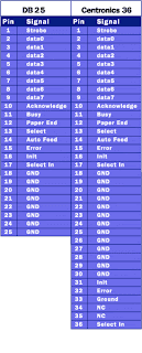
When a PC sends data to a printer or other device using a parallel port, it sends 8 bits of data (1 byte) at a time. These 8 bits are transmitted parallel to each other, as opposed to the same eight bits being transmitted serially (all in a single row) through a serial port. The standard parallel port is capable of sending 50 to 100 kilobytes of data per second.

Let's take a closer look at what each pin does when used with a printer:
  • Pin 1 carries the strobe signal. It maintains a level of between 2.8 and 5 volts, but drops below 0.5 volts whenever the computer sends a byte of data. This drop in voltage tells the printer that data is being sent.
  • Pins 2 through 9 are used to carry data. To indicate that a bit has a value of 1, a charge of 5 volts is sent through the correct pin. No charge on a pin indicates a value of 0. This is a simple but highly effective way to transmit digital information over an analog cable in real-time.
  • Pin 10 sends the acknowledge signal from the printer to the computer. Like Pin 1, it maintains a charge and drops the voltage below 0.5 volts to let the computer know that the data was received.
  • If the printer is busy, it will charge Pin 11. Then, it will drop the voltage below 0.5 volts to let the computer know it is ready to receive more data.
  • The printer lets the computer know if it is out of paper by sending a charge on Pin 12.
  • As long as the computer is receiving a charge on Pin 13, it knows that the device is online.
  • The computer sends an auto feed signal to the printer through Pin 14 using a 5-volt charge.
  • If the printer has any problems, it drops the voltage to less than 0.5 volts on Pin 15 to let the computer know that there is an error.
  • Whenever a new print job is ready, the computer drops the charge on Pin 16 to initialize the printer.
  • Pin 17 is used by the computer to remotely take the printer offline. This is accomplished by sending a charge to the printer and maintaining it as long as you want the printer offline.
  • Pins 18-25 are grounds and are used as a reference signal for the low (below 0.5 volts) charge.

Notice how the first 25 pins on the Centronics end match up with the pins of the first connector. With each byte the parallel port sends out, a handshaking signal is also sent so that the printer can latch the byte.

The Serial Connection

The external connector for a serial port can be either 9 pins or 25 pins. Originally, the primary use of a serial port was to connect a modem to your computer. The pin assignments reflect that. Let's take a closer look at what happens at each pin when a modem is connected.


Close-up of 9-pin and 25-pin serial connectors
9-pin connector: (Pin Nos.)
  1. Carrier Detect - Determines if the modem is connected to a working phone line.

  2. Receive Data - Computer receives information sent from the modem.

  3. Transmit Data - Computer sends information to the modem.

  4. Data Terminal Ready - Computer tells the modem that it is ready to talk.

  5. Signal Ground - Pin is grounded.

  6. Data Set Ready - Modem tells the computer that it is ready to talk.

  7. Request To Send - Computer asks the modem if it can send information.

  8. Clear To Send - Modem tells the computer that it can send information.

  9. Ring Indicator - Once a call has been placed, computer acknowledges signal (sent from modem) that a ring is detected.

25-pin connector: (Pin Nos.)

  1. Not Used

  2. Transmit Data - Computer sends information to the modem.

  3. Receive Data - Computer receives information sent from the modem.

  4. Request To Send - Computer asks the modem if it can send information.

  5. Clear To Send - Modem tells the computer that it can send information.

  6. Data Set Ready - Modem tells the computer that it is ready to talk.

  7. Signal Ground - Pin is grounded.

  8. Received Line Signal Detector - Determines if the modem is connected to a working phone line.

  9. Not Used: Transmit Current Loop Return (+)

  10. Not Used

  11. Not Used: Transmit Current Loop Data (-)

  12. Not Used

  13. Not Used

  14. Not Used

  15. Not Used

  16. Not Used

  17. Not Used

  18. Not Used: Receive Current Loop Data (+)

  19. Not Used

  20. Data Terminal Ready - Computer tells the modem that it is ready to talk.

  21. Not Used

  22. Ring Indicator - Once a call has been placed, computer acknowledges signal (sent from modem) that a ring is detected.

  23. Not Used

  24. Not Used

  25. Not Used: Receive Current Loop Return (-)

Voltage sent over the pins can be in one of two states, On or Off. On (binary value "1") means that the pin is transmitting a signal between -3 and -25 volts, while Off (binary value "0") means that it is transmitting a signal between +3 and +25 volts...

Microelectronics

Microelectronics is a subfield of electronics. Microelectronics, as the name suggests, is related to the study and manufacture of electronic components which are very small. These devices are made from semiconductors using a process known as photolithography. Many components of normal electronic design are available in microelectronic equivalent: transistors, capacitors, inductors, resistors, diodes and of course insulators and conductors can all be found in microelectronic devices.
Digital integrated circuits consist mostly of transistors. Analog circuits commonly contain resistors and capacitors as well. Inductors are used in some high frequency analog circuits, but tend to occupy large chip area if used at low frequencies; gyrators can replace them.
As techniques improve, the size of microelectronic components continue to decrease. At smaller scales, the effects of minor circuit elements such as interconnections may become more important. These are called parasitic effects, and the goal of the microelectronics design engineer is to find ways to compensate for or to minimize these effects, while always delivering smaller, faster, and cheaper devices.

Nematic Phase Liquid Crystals

Just as there are many varieties of solids and liquids, there is also a variety of liquid crystal substances. Depending on the temperature and particular nature of a substance, liquid crystals can be in one of several distinct phases (see below). In this article, we will discuss liquid crystals in the nematic phase, the liquid crystals that make LCDs possible.
One feature of liquid crystals is that they're affected by electric current. A particular sort of nematic liquid crystal, called twisted nematics (TN), is naturally twisted. Applying an electric current to these liquid crystals will untwist them to varying degrees, depending on the current's voltage. LCDs use these liquid crystals because they react predictably to electric current in such a way as to control light passage.

Liquid Crystal Types

Most liquid crystal molecules are rod-shaped and are broadly categorized as either thermotropic or lyotropic. Thermotropic liquid crystals will react to changes in temperature or, in some cases, pressure. The reaction of lyotropic liquid crystals, which are used in the manufacture of soaps and detergents, depends on the type of solvent they are mixed with. Thermotropic liquid crystals are either isotropic or nematic. The key difference is that the molecules in isotropic liquid crystal substances are random in their arrangement, while nematics have a definite order or pattern.

The orientation of the molecules in the nematic phase is based on the director. The director can be anything from a magnetic field to a surface that has microscopic grooves in it. In the nematic phase, liquid crystals can be further classified by the way molecules orient themselves in respect to one another. Smectic, the most common arrangement, creates layers of molecules. There are many variations of the smectic phase, such as smectic C, in which the molecules in each layer tilt at an angle from the previous layer. Another common phase is cholesteric, also known as chiral nematic. In this phase, the molecules twist slightly from one layer to the next, resulting in a spiral formation.

Ferroelectric liquid crystals (FLCs) use liquid crystal substances that have chiral molecules in a smectic C type of arrangement because the spiral nature of these molecules allows the microsecond switching response time that make FLCs particularly suited to advanced displays. Surface-stabilized ferroelectric liquid crystals (SSFLCs) apply controlled pressure through the use of a glass plate, suppressing the spiral of the molecules to make the switching even more rapid.

Radio Spectrum

You've probably heard about "AM radio" and "FM radio," "VHF" and "UHF" television, "citizens band radio," "short wave radio" and so on. Have you ever wondered what all of those different names really mean? What's the difference between them?
In this article, we will look at the radio spectrum and see what is really going on.

Radio Frequencies
A radio wave is an electromagnetic wave propagated by an antenna. Radio waves have different frequencies, and by tuning a radio receiver to a specific frequency you can pick up a specific signal.
In the United States, the FCC (Federal Communications Commission) decides who is able to use which frequencies for which purposes, and it issues licenses to stations for specific frequencies.
When you listen to a radio station and the announcer says, "You are listening to 91.5 FM WRKX The Rock!," what the announcer means is that you are listening to a radio station broadcasting an FM radio signal at a frequency of 91.5 megahertz, with FCC-assigned call letters of WRKX. Megahertz means "millions of cycles per second," so "91.5 megahertz" means that the transmitter at the radio station is oscillating at a frequency of 91,500,000 cycles per second. Your FM (frequency modulated) radio can tune in to that specific frequency and give you clear reception of that station. All FM radio stations transmit in a band of frequencies between 88 megahertz and 108 megahertz. This band of the radio spectrum is used for no other purpose but FM radio broadcasts.
In the same way, AM radio is confined to a band from 535 kilohertz to 1,700 kilohertz (kilo meaning "thousands," so 535,000 to 1,700,000 cycles per second). So an AM (amplitude modulated) radio station that says, "This is AM 680 WPTF" means that the radio station is broadcasting an AM radio signal at 680 kilohertz and its FCC-assigned call letters are WPTF.
Common frequency bands include the following:
  • AM radio - 535 kilohertz to 1.7 megahertz

  • Short wave radio - bands from 5.9 megahertz to 26.1 megahertz

  • Citizens band (CB) radio - 26.96 megahertz to 27.41 megahertz

  • Television stations - 54 to 88 megahertz for channels 2 through 6

  • FM radio - 88 megahertz to 108 megahertz

  • Television stations - 174 to 220 megahertz for channels 7 through 13

What is funny is that every wireless technology you can imagine has its own little band. There are hundreds of them! For example:


Deep space radio communications: 2290 megahertz to 2300 megahertz
Why is AM radio in a band at 550 kilohertz to 1,700 kilohertz, while FM radio is in a band at 88 to 108 megahertz? It is all completely arbitrary, and a lot of it has to do with history.
AM radio has been around a lot longer than FM radio. The first radio broadcasts occurred in 1906 or so, and frequency allocation for AM radio occurred during the 1920s (The predecessor to the FCC was established by Congress in 1927.). In the 1920s, radio and electronic capabilities were fairly limited, hence the relatively low frequencies for AM radio.
Television stations were pretty much non-existent until 1946 or so, which is when the FCC allocated commercial broadcast bands for TV. By 1949, a million people owned TV sets, and by 1951 there were 10 million TVs in America.
FM radio was invented by a man named Edwin Armstrong in order to make high-fidelity (and static-free) music broadcasting possible. He built the first station in 1939, but FM did not become really popular until the 1960s. Hence the higher frequencies for FM radio.

The difference between a fluorescent light and a neon light

A neon light is the sort of light you see used in advertising signs. These signs are made of long, narrow glass tubes, and these tubes are often bent into all sorts of shapes. The tube of a neon light can spell out a word, for example. These tubes emit light in different colors.
A fluorescent light, on the other hand, is most often a long, straight tube that produces white light. You see fluorescent lights in offices, stores and some home fixtures.
The idea behind a neon light is simple. Inside the glass tube there is a gas like neon, argon or krypton at low pressure. At both ends of the tube there are metal electrodes. When you apply a high voltage to the electrodes, the neon gas ionizes, and electrons flow through the gas. These electrons excite the neon atoms and cause them to emit light that we can see. Neon emits red light when energized in this way. Other gases emit other colors.
A fluorescent light works on a similar idea but it has an extra step. Inside a fluorescent light is low-pressure mercury vapor. When ionized, mercury vapor emits ultraviolet light. Human eyes are not sensitive to ultraviolet light (although human skin is -- see How Sunburns and Sun Tans Work!). Therefore, the inside of a fluorescent light is coated with a phosphor. A phosphor is a substance that can accept energy in one form (for example, energy from a high-speed electron as in a TV tube -- see How Television Works) and emit the energy in the form of visible light. In a fluorescent lamp, the phosphor accepts the energy of ultraviolet photons and emits visible photons.
The light we see from a fluorescent tube is the light given off by the phosphor that coats the inside of the tube (the phosphor fluoresces when energized, hence the name). The light of a neon tube is the colored light that the neon atoms give off directly.